


- Site Navigation -
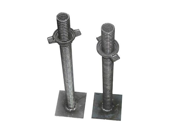
Cuplock Prop Head
The Cuplock Prop Head (also referred to as Cuplock Adjustable Head or Cuplock Top Support) is a specialized, integrated load-bearing and connection component designed exclusively fo......
The Cuplock Prop Head (also referred to as Cuplock Adjustable Head or Cuplock Top Support) is a specialized, integrated load-bearing and connection component designed exclusively for cuplock scaffold systems—a widely used modular scaffolding solution in construction. As the "top terminal" of cuplock scaffold Vertical pole s, it combines the functions of height adjustment, load transmission, and secure connection to formwork or working platforms. Its core feature is compatibility with the cuplock system’s unique cup-and-wedge connection, enabling quick assembly, stable load-bearing, and precise height fine-tuning, making it indispensable for cuplock-based formwork support, high-altitude operation platforms, and temporary structural bracing.
Typical Application Scenarios
The Cuplock Prop Head is tailored to the scenarios where cuplock scaffolds excel—modular, high-stability, and rapid-assembly requirements. Its main applications include:
Cuplock-Based Formwork Support: Used as the top support for cuplock scaffold Vertical pole s in floor slab, beam, and column formwork systems. It bears the load of concrete, formwork panels, and joists, with height adjustment ensuring precise alignment of formwork elevation.
High-Altitude Working Platforms: In cuplock scaffolds for maintenance, painting, or installation work (e.g., building facades, bridge decks), it supports the platform’s wooden planks or steel decks, providing a stable working surface.
Large-Span Structure Bracing: Temporary bracing for prefabricated concrete beams, steel trusses, or bridge segments during installation. The cuplock system’s rigidity, combined with the prop head’s load capacity, prevents structural displacement.
High-Formwork Systems: In high-rise buildings (floor height> 6m) or large-space structures (e.g., shopping malls, auditoriums), it collaborates with heavy-duty cuplock Vertical pole s to form a stable vertical support network, withstanding large cumulative loads.
Installation & Usage Guidelines
To ensure the safety and efficiency of the cuplock system, the Cuplock Prop Head must be installed and used in strict accordance with the following rules:
Ensure Compatibility with Cuplock Vertical pole: Select a prop head whose base sleeve diameter matches the cuplock Vertical pole (e.g., Φ48mm sleeve for Φ48mm Vertical pole). Never force a mismatched prop head onto the Vertical pole,as this will damage the connection and reduce stability.
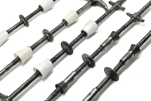
Secure Lead Screw Insertion: The lead screw must be inserted into the base sleeve to a depth of ≥100mm (or per the manufacturer’s recommendation). Insufficient insertion will weaken load-bearing capacity and risk disengagement.
Align Vertically: Install the prop head so that the lead screw and base sleeve are perpendicular to the ground (verticality deviation ≤ 0.5°). Eccentric installation (tilted) will cause uneven load distribution, leading to lead screw bending or base sleeve deformation.
Tighten Adjusting Nut and Lock: After adjusting to the required height, use a wrench to fully tighten the adjusting nut. For high-vibration environments (e.g., concrete pumping), install the optional locknut or anti-loosening pin to prevent nut slippage due to vibration.
Even Load Distribution: Ensure the top bearing plate is fully in contact with the supported object (e.g., formwork joist, platform plank). If there is a gap, use a thin steel plate or wooden shim to fill it—avoid partial contact, which causes eccentric loading.
Never Overload: Strictly adhere to the rated load (check the product’s test report). For example, a 20kN prop head cannot be used for a 25kN load, as this may result in thread failure, lead screw fracture, or cuplock connection collapse.
Inspect Before Assembly: Before installation, check for defects: (1) Cracks or deformation in the cuplock base sleeve or top bearing plate; (2) Bent lead screw or damaged threads; (3) Loose welds between the base sleeve and lead screw; (4) Worn or cracked adjusting nuts. Damaged prop heads must be discarded immediately.
Maintenance & Storage
Proper maintenance and storage extend the service life of the Cuplock Prop Head and ensure its performance:
Clean After Use: Remove concrete residue, dust, or dirt from the base sleeve, lead screw, and nut using a wire brush or compressed air. For threaded parts, apply a thin layer of anti-rust oil (e.g., machine oil) to prevent rust and thread seizure.
Classified Storage: Store prop heads in a dry, ventilated warehouse (avoid direct sunlight, rain, or humidity). Classify them by size (e.g., base sleeve diameter, lead screw length) and mark clearly to avoid confusion during later use.
Regular Inspection: Conduct semi-annual inspections of stored prop heads: (1) Check for rust on the lead screw and base sleeve (remove light rust with sandpaper; discard heavily rusted parts); (2) Test thread smoothness (rotate the nut to ensure no jamming); (3) Verify weld integrity (check for cracks at reinforcement ribs).

Contact Us
Tel:+86-15831733891
E-mail:yichengbuildingmaterials@gmail.com
Add:100 meters south of Weicun Village, Hechengjie Town, Xian County, Cangzhou City, Hebei Province
Url:https://www.yc-buildingmaterials.com