- Site Navigation -
NEWS LIST
What Are the Tolerance Limits for Steel Support Installation?
Author:yicheng Date:2025-09-03 18:11:55 Hits:54
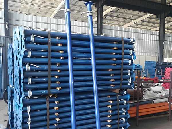
Tolerance Limits for Steel Support Installation
Tolerance limits for steel support installation in bridge engineering are strictly defined to ensure structural safety, load-bearing capacity, and long-term stability. These limits vary slightly based on bridge type (e.g., beam bridges, cable-stayed bridges), support types (e.g., piers, abutments, bearing supports), and industry standards (e.g., AASHTO in the U.S., Eurocode in Europe, GB standards in China). Below is a structured breakdown of key tolerance categories and typical limits:
1. Dimensional Tolerances for Support Components
These apply to prefabricated steel support parts (e.g., base plates, column shafts, connection brackets) before and after installation, ensuring they fit with adjacent structures (e.g., bridge girders, foundations).
Steel Column Shaft: Vertical straightness is critical to avoid uneven load distribution. The allowable deviation is ≤ L/1000 (where L = column height), with a maximum limit of 15mm (per AASHTO LRFD standards). For example, a 10m-tall column can deviate by no more than 10mm vertically.
Base Plate: The flatness of the bearing surface (which contacts the foundation or grout layer) directly impacts load transfer. Tolerances are ≤ 3mm per meter of plate length (Eurocode 3), with no local 凸起 (bulges) exceeding 1mm—small unevenness here can cause “point loading” on the foundation, leading to cracking.
Connection Holes: For bolted joints (common in steel support connections), hole position deviation is limited to ≤ ±1mm to ensure bolts align with mating components. Hole diameter tolerance is stricter, at ±0.5mm—oversized or undersized holes prevent proper bolt seating and reduce joint strength.
Support Height: Deviation from the design elevation (critical for bearing supports that rest under bridge girders) is ≤ ±5mm. For larger supports like piers, the tolerance is slightly more flexible at ≤ ±10mm, but still tightly controlled to avoid misaligning the bridge deck.
2. Positional Tolerances (Horizontal & Vertical Alignment)
Positional accuracy ensures steel supports align with the bridge’s overall structural layout, preventing uneven stress on girders, cables, or foundations.
Horizontal Position Deviation:
For major load-bearing supports (piers, abutments), the allowable deviation from the design centerline is ≤ ±20mm (per GB 50205-2020, China’s key standard for steel structure installation). This prevents the bridge deck from shifting laterally and overloading one side of the support.
For secondary supports (e.g., lateral bracing that stabilizes piers), the tolerance is more lenient at ≤ ±30mm, as they carry less direct load.
For curved bridges, radial alignment (following the bridge’s curve) has an additional limit of ≤ ±15mm per 10m span—this ensures the support follows the curve’s radius and avoids twisting the deck.
Vertical Levelness:
Bearing support surfaces (where bridge girders rest) require extreme flatness to distribute deck loads evenly. The allowable slope is ≤ 2mm per meter (AASHTO standards)—a steeper slope would cause the girder to “rock” and concentrate stress on one edge of the support.
Base plates on concrete foundations have a total vertical deviation limit of ≤ 3mm across the entire plate. This ensures the base plate makes full contact with the grout layer (used to fill small gaps), avoiding voids that weaken load transfer.
3. Tolerances for Connection Joints
Steel supports rely on bolted, welded, or riveted joints to connect to other components—tolerances here prevent loose connections, stress concentration, or joint failure.
Bolted Joints:
Bolt hole misalignment is strictly limited to ≤ 1mm. Forced insertion of bolts (to compensate for misalignment) bends the bolts and introduces shear stress, reducing their ability to resist loads.
Bolt torque (the force used to tighten bolts) has a tolerance of ±10% of the design value. For example, if the design torque is 500 N·m, the acceptable range is 450–550 N·m. Under-tightening leads to loose joints; over-tightening strips threads or damages the bolt.
Welded Joints:
Weld bead size (measured by throat thickness, the critical dimension for load-bearing) has a tolerance of ±1mm of the design value (Eurocode 3). A smaller throat reduces joint strength, while an oversized bead adds unnecessary weight and may introduce defects like porosity.
Weld misalignment (the offset between the two steel parts being welded) is limited to ≤ 3mm for plates ≤ 20mm thick, and ≤ 5mm for thicker plates. Excessive misalignment creates bending stress in the joint, accelerating fatigue.
4. Special Tolerances for Dynamic/High-Load Supports
For bridges subject to heavy loads (e.g., railways) or dynamic forces (e.g., seismic zones), stricter tolerances apply to ensure supports can withstand extreme conditions.
Seismic Supports:
Lateral displacement limits are ≤ 5mm (AASHTO LRFD Seismic Design). Seismic supports (e.g., dampers, shear keys) rely on precise positioning to absorb earthquake energy—even small displacement can render them ineffective, leading to deck collapse.
Vertical elevation deviation is ≤ ±3mm to maintain the support’s intended energy-dissipating capacity; a lower or higher position changes how forces are transferred during an earthquake.
Railway Bridge Supports:
Horizontal alignment tolerance is stricter at ≤ ±10mm (compared to highway bridges) to prevent rail misalignment. Railway tracks require minimal lateral movement, so supports must stay within narrow limits to avoid derailment risks.
Long-term settlement (slow sinking of the support after installation) is limited to ≤ 2mm per year. Excessive settlement would create uneven track surfaces, increasing wear on trains and tracks.
5. Tolerance Inspection Methods
To verify compliance, inspectors use specialized tools tailored to each tolerance type:
Dimensional checks: Vernier calipers (for hole diameter), tape measures (for support height), and laser distance meters (for long-span length).
Straightness/levelness: Laser levels (precision ±0.5mm/m) for vertical columns, spirit levels for base plates, and total stations (surveying tools) for horizontal alignment of piers across large distances.
Joint checks: Torque wrenches (to verify bolt tightness), ultrasonic testing (to detect hidden weld defects), and feeler gauges (to measure gaps between connected parts).
In summary, steel support installation tolerances balance structural performance with practical constructability—they are not arbitrary, but rooted in preventing premature fatigue, uneven load distribution, or catastrophic failure. Strict adherence to standards and on-site inspection are non-negotiable to ensure the bridge’s long-term safety and durability.


