- Site Navigation -
NEWS LIST
What Are the Tolerance Limits for Steel Support Installation?
Author:yicheng Date:2025-09-03 18:06:44 Hits:97
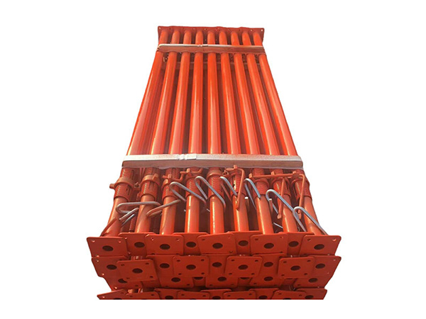
Tolerance Limits for Steel Support Installation
Tolerance limits for steel support installation define the allowable deviation from design specifications—critical for ensuring structural safety,load-bearing capacity,and compatibility with other bridge or building components.These limits vary by support type(e.g.,columns,beams,bracings)and industry standards(e.g.,AISC in the U.S.,BS EN in the EU,GB in China),but core parameters and general ranges are consistent across projects.Below is a breakdown of key tolerance categories and typical limits:
1.Dimensional Tolerances(Linear&Cross-Sectional)
Dimensional tolerances control deviations in the physical size of steel supports,preventing mismatches with connecting parts(e.g.,girders,foundations)and ensuring uniform load distribution.
Length Tolerance:For steel columns,beams,or bracings,length deviations are typically tied to their total length.For supports under 10 meters,the allowable deviation is often±3mm;for lengths between 10–20 meters,it extends to±5mm;and for supports over 20 meters,±8mm(per AISC 360-10).This prevents excessive gaps or compression when joining supports to foundations or superstructures.
Cross-Sectional Tolerances:For common shapes like I-beams,H-columns,or square tubes,deviations in width,height,or thickness are strictly limited.For example,the flange width of an I-beam(e.g.,W14×90)may have an allowable deviation of±1.5mm,while the web thickness(a critical load-bearing part)allows±0.8mm.For hollow steel supports(e.g.,circular tubes),outer diameter tolerance is usually±1%of the design diameter(e.g.,±1mm for a 100mm-diameter tube),ensuring consistency in bending and torsional strength.
2.Positional Tolerances(Alignment&Placement)
Positional tolerances ensure steel supports are installed in the correct spatial location,avoiding uneven load stress or structural misalignment.
Vertical Alignment(Plumbness):Vertical supports(e.g.,columns,bridge pylons)must maintain plumbness to resist compressive and lateral loads.For columns up to 10 meters tall,the allowable deviation from vertical is≤1/1000 of the height(e.g.,≤10mm for a 10m column);for heights over 10 meters,it is≤1/1500 of the height(e.g.,≤13mm for a 20m column).For high-rise bridge pylons(50m+),stricter limits(≤1/2000)apply to prevent wind-induced sway or uneven cable tension.
Horizontal Alignment:Horizontal supports(e.g.,beams,bracings)must align with design coordinates to ensure proper connection to vertical supports.The allowable lateral deviation(left/right of the design line)is typically±5mm for spans under 10 meters and±8mm for spans over 10 meters.For bridge deck supports(e.g.,cross-beams),longitudinal deviation(along the bridge’s length)is limited to±3mm to avoid mismatches with deck panels.
Foundation Connection Position:Steel supports anchored to concrete foundations(via anchor bolts or base plates)have strict position tolerances for base plates.The centerline of the base plate relative to the foundation’s design center must deviate by≤5mm,and the bolt hole positions on the base plate(critical for securing the support)allow±2mm deviation—preventing bolt misalignment and uneven load transfer to the foundation.
3.Flatness&Straightness Tolerances
These tolerances ensure steel supports have smooth,uniform surfaces and linearity,avoiding stress concentrations at joints or weak points.
Base Plate Flatness:The bottom surface of a steel support’s base plate(which sits on the foundation)must be flat to distribute load evenly.The allowable flatness deviation is≤2mm per meter of plate length(e.g.,≤6mm for a 3m-long base plate).Uneven base plates can cause"point loading"on the foundation,leading to concrete cracking.
Support Straightness:For linear supports(e.g.,beams,bracings),straightness deviation(bowing or bending along the length)is limited to≤1mm per meter of length.For example,a 15m-long steel beam can have a maximum bow of 15mm.Excessive straightness deviation reduces the support’s ability to resist bending loads and may cause gaps at connections.
4.Welding&Connection Tolerances
Steel supports are often joined via welding or bolted connections;tolerances here ensure joint strength and stability.
Weld Seam Tolerances:For fillet welds(common in bracings),the leg length(a key measure of weld strength)allows±1mm deviation from the design size(e.g.,a 6mm leg weld can range from 5–7mm).For butt welds(used in beam splices),the alignment of the two steel pieces(root gap)must deviate by≤1mm—excessive gaps weaken the weld and increase the risk of cracking.
Bolted Connection Tolerances:Bolt holes in steel supports must align with holes in connecting components(e.g.,girders).The allowable misalignment between paired holes is≤1mm for high-strength bolts(e.g.,A325,8.8-grade),as misalignment forces bolts to bear shear stress,reducing their load capacity.
Key Standards&Project-Specific Adjustments
Tolerance limits are not universal—they are governed by regional standards(e.g.,AISC 360-10,BS EN 1090-2,GB 50205)and refined by project requirements:
For seismic zones,tolerances are stricter(e.g.,plumbness≤1/2000 for columns)to ensure supports can absorb seismic energy without collapsing.
For long-span bridges,horizontal alignment tolerances for main beam supports are tightened(±3mm)to maintain cable tension balance in cable-stayed or suspension bridges.
On-site,tolerances are verified using tools like laser levels(for plumbness),total stations(for position),calipers(for cross-sections),and straightedges(for flatness).Any deviation exceeding limits requires corrective action(e.g.,trimming,re-welding,or shimming)before the support is deemed compliant.


